
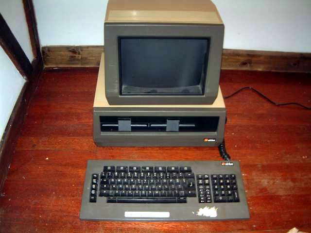
The Sirius 1 (or Victor 9000 in the US) was an excellent machine for 1982. Designed by Sirius Technologies which was the company
set up by Chuck Peddle when he left MOS/Commodore, it featured an Intel 8088 CPU, 128K of dynamic RAM, hi-res graphics, speech capability and a
completely new innovation - multi speed floppies that could store much more than contemporary units of the day. Typically, floppies then were 110k or 360k
in capacity, double sided drives took this up to 720k per disk.
However the Sirius' own controller split the disk into 8 'zones' with different bit densities for each zone as the tracks moved
to the outside of the disk. This means that if you altered the speed of the drive itself depending on the zone you were in you could vastly increase
capacity, so the Sirius drives could store up to 1.2mb per DSDD disk. The High Density or HD drive did appear in 1982 and could also hold 1.2MB per disk,
but you needed DSHD disks for these drives which were a lot more expensive.
 |  |  |  |
 |  |  |  |
I've had the Sirius 1 at the top since 2005 when it was graciously given to me by Gareth Randall before the family emigrated to sunnier climes. It's a standard machine with double sided floppies and an extra RAM/ROM board containing 128K expanded memory.
When I first powered it up the biggest RIFA mains capacitor in the PSU exploded and the high speed of the cooling fan ensured
the smoke was well distributed around my house in minutes :D
Back in those days I replaced like for like so swapped every RIFA in the supply. Last year (2021) I pulled out the machine to restore it and this time
while fixing the 5V rail in the PSU I also replaced the RIFAs with modern capacitors that should last far longer than I will. The machine ran for a few
days then decided it had had enough and refused to acknowledge its floppy drives. Back into storage with it as I was still wary of working on it as
service information was fairly scant.
Come 2022 and @schoenfeld_jens found his Service Manual and uploaded the whole thing, splendid! Suddenly I had schematics and the
theory of operation so I could use my oscilloscope to watch the data bus on the floppy controller and was pretty sure one of the three 6522 VIA chips on
the board had failed. Meanwhile I was followed home one day by a pair of new (to me) machines, a white one and another brown one that could best be
described as 'foxed'.
Repair time!
With my scope showing me there was activity on the data bus on the controller even with no host connected I took a punt at the
middle of the 3 6522s being bad since that's the one that's being selected at boot time, the 'gateway' to the controller. Of course, one of the other
two could also have been spiking the bus but I was lucky and after changing 1H the machine returned to booting status. Marvellous.
Both the new machines had unknown condition PSUs so I used my one good one to power up the white machine. It wasn't running
enough code to get to the point of selecting 0xE8000 to access the floppies so it was time to hook it up to my HP logic analyser to see how much code it
WAS running. The source code for the f3f6 universal ROM in the machine was online so thanks to @fozztexx for producing a version that
would compile and link on Linux. With the help of @mackjsy and a few others I got to grips with the Ghidra disassembler and eventually
produced a code stream I could follow with the analyser. See links below.
The machine wasn't getting past address 0x0202 on a RAM test, see analyser pics below. The RAM test writes AA55 to each location
and naturally expects to read that back. In this case it was getting AA15 back which meant D6 was stuck:
0x55 in hex is 01010101 in binary.
0x15 in hex is 00010101. The difference is D6, counting from D0 on the right. It's stuck at 0.
I'd already identified and swapped obviously dead RAM chips (DOUT was permanently high) so now it was time to find marginal ones. I ended up swapping 14 of the 16 chips on board, including D6, but finally got a pulse on the enable pin of the 74LS245 driver at 11K that controls access to the floppy controller!
 |  |  |  |
 |  )") |  |  |
 |  |  |  |
 |
It Boots!
Afer a 'woop' I refitted the floppy enclosure and the machine booted! I serviced the PSU and that machine was now complete, aside
from requiring the expected keyboard foam'n'foil discs which I ordered from TexElec. The 512k RAM board worked first time too, which surprised me since
I'd initially been 'borrowing' chips from it to test the on-board RAM before I bought more spares. Both DOS2 and CPM/86 booted fine, and I even had
a DOS version of WordStar 3.0 to show off.
 |  |  |  |
 |  |  |
Foxed Repair
The 'foxed' machine span drive 0 constantly and wouldn't boot, but curiously WOULD boot from drive 1. Examining the schematic
and theory of operation I could see what the control signals were supposed to do and what the Intel D8748 microcontroller on the floppy board was
expecting. With the help of my little 16 channel analyser I could see that the signal to start and stop drive 0 was being ignored. Aside from this,
because drive 0 was on constantly the tachometer reading at the microcontroller was outside threshold so the drive never became ready anyway. This meant
that either the op-amp (3A) controlling the TIP32A transistor (Q1) that switched the motor on was bad or the transistor itself was bad.
Typical me, I picked the wrong one to check first. Since I'd been on a roll swapping chips and had already tested the 6522
at 1F (interface to the drives) I swapped the pair of LM2917 op-amps which is why you can see 3A and 3C the wrong way round in the first pic, if drive
0's op-amp (3A) was bad then the fault would switch to drive 1. It didn't, so the only thing left was the TIP32A transistor at Q1. Sure enough it was
running a steady voltage of around 6V which a) it shouldn't at powerup and b) isn't enough for the tachometer reading to ever make the drive ready. Once
some spares arrived I swapped Q1 and lo, the drive started behaving itself and the machine booted successfully :D I'd already fixed its PSU so that's
3 machines complete and working.
 | . There's only 2 components that can cause this - the LM2917 op-amp at 3A and the TIP32A transistor at 1Q.") |  |  |
 |  |
Original Sirius Repair
I'd like to thank the company that did the wave soldering on the Sirius boards for making it such a pleasure to remove and test
all the 6522s on the floppy board. I suspected the middle one (1H) but when I removed it and tested it in my Test PET it worked. So I removed 1H and 1K
as well. Which also worked. Then I learned that the PET only does very basic checks on the 6522 and if one of the ports is dead it might not be found,
so I socketed and returned 1H and 1K then swapped 1H for a new one. Success!
 |  |
Links
White Sirius ROM (8K), version F3F6
Disassembly listing of the White Sirius ROM, boot parts annotated with comments/routine names from the source code
Original dump of 5H ROM (4K) in the white Sirius
Original dump of 7H ROM (4K) in the white Sirius Universal ROM-LO, version F3F7
Universal ROM-HI, version F3F7
Disassembly listing of the White Sirius ROM, boot parts annotated with comments/routine names from the source code
Original dump of 5H ROM (4K) in the white Sirius
Original dump of 7H ROM (4K) in the white Sirius Universal ROM-LO, version F3F7
Universal ROM-HI, version F3F7
All images and text © Adrian Graham 1999-2024 unless otherwise noted using words. Also on 
