
*UPDATE May 2021*
I've been working furiously at recovering the source code from the floppies i got in my Mega-Haul in 2016. See
here for details. I had to write it all down before I forgot what I'd done.
History (originally written in 2016)
Standard Telephone & Cable made quite a few phones for British Telecom in the 70s/80s that most people will
recognise instantly even though they didn't actually know who made them. Probably like me they thought that BT made all their own
stuff which I later found out was completely wrong but hey. In the early 80s they branched out into computerised telephones with
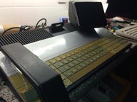
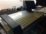
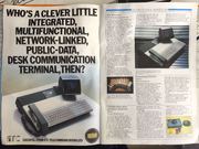
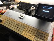
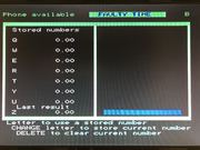
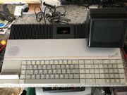
this lovely looking beast, the Executel 3910.
David Leevers is the man who designed the hardware, and after I'd tracked him down he said "I built
the first prototype Executel as a commodore Pet, second one was an Apple 2 with small teletext screen in place of the clip on top,
came out in 1984, they built 10,000 but only sold 5000, ahead of its time, cost £6,000 in todays money. I doubt whether the tape
transport still works but the telephone side is OK." Happily the telephone side is still very happy today, see later updates.
I'd *love* to have seen the Apple][ with the clip-on screen! Obviously my curiosity is piqued as to what
happened to the unsold ones. Industrial design, ie the case, was by Robert Cross of Cross Almond and Partners, and they were determined to
make the machine look different to other telephone systems. I think they succeeded! So did the Design Council who gave them a gold award
in 1984.
Fellow collector Tony brought this one to my attention and on seeing the pictures I said
'what the hells is THAT!' and bought it. It's a desk phone, pure and simple, but very computerised with an 8085a processor
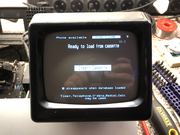
and 32K RAM plus a 5" monitor for displaying diary and phonebook entries AND, and it's a big AND, PRESTEL access!
Back in those days PRESTEL was a big deal and was pushed by the likes of Plessey Communications, Philips
and Mullard who made chipsets for set-top boxes to access this fledgling information superhighway - very pre-internet. It didn't really take
off though because it relied on the phone network and phone calls were expensive meaning it was only used by businesses.
Note this is different to the Teletext service people remember on their TVs. Several banks tried to push Prestel as a means of
online banking and provided terminals like the Tandata TD1400 to let you manage your accounts from the comfort of your
armchair though please ask the phone bill payer before calling :) It cost 50p per PAGE.
The Viewdata processor is the Plessey MR9735-02 which handled the display of stored pages in its own 1K
RAM and directly drives the 5" B&W screen. Tony's unit also has a small board fitted that allowed an external RGB monitor to be
connected via SCART.
Communications came courtesy of the Philips (now Signetics) SAA5070 "LUCY" chip which could do 1200/75 baud
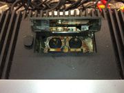
modem duties to talk to the outside world amongst other things. More Intel D8741 microprocessors powered the keyboard and tape transport which
was also made by Philips. In total this machine has 4 processors, not bad for 1984!
Whilst looking around for people who might've had something to do with the Executel I came across two
names, one still active and one that's disappeared. John Staniland Burton used to run Aston Communications; they
seemed to pride themselves on servicing and repairing Executels. These days their website is a single broken page but I'd love to
get in contact with him.
The other name is Sean Newcombe whose bio says not only was he at STC and oversaw the
design of the Executel but also oversaw the design of the ICL One-Per-Desk a couple of years later after STC bought ICL. I'd been
led to believe the two machines were totally separate but...
These days they're mostly to be found in museums, even the National Trust has one in one of their more
contemporary houses in Esher, Surrey. Since owning some I've become aware of people who still use them as their main house phone, which is splendid.
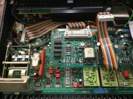
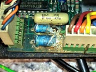
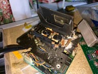
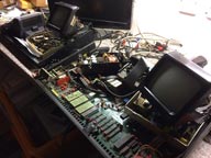
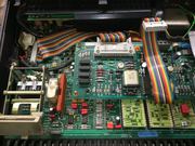
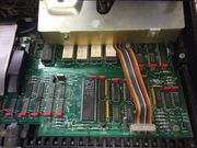
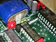
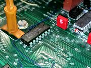
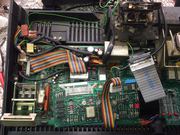
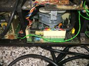
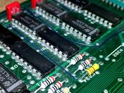
Unfortunately plastic hides a multitude of storage sins and this one's internals looked like it had been
kept on its back in a pond since some of the components had rotted. What made things worse was the seller I bought it from had
tried to power it up and let out the magic smoke...the keyboard had also been very wet in the past so I was fearful for its condition.
Restoration
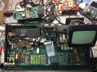
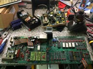
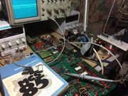
Vertical learning curve time. Over the months I've drawn out the whole computer side of the system board
in an attempt to learn what it does and identify the chips that have lost their markings. Fortunately I could read all the ROMs
before two of them expired and have disassembled all of the code. Some of the components are difficult to find any info on,
particularly the MR9735 and SAA5070 which seem to have been largely forgotten. Programming details on both of them are restricted
to a single datasheet but thankfully for the MR9735 it was also used by Tandata in their TD series of teletext adapters so at least
I could test it. I've since discovered that the SAA5070 LUCY chip is also used in the Tantel, Tandata's first foray into Viewdata.
One thing I'm really missing is the memory map because the 8085 can address 64K of memory and in this
machine's case the bottom 32K is ROM (4x 8K EEPROMs) and the upper 32K is RAM (16x 4116 DRAM), but in amongst that you also have
the 1K of page store for the teletext chip, some space also needs to be reserved for the realtime clock on board and there's other
sundries going on too. Also upper RAM in the $FB00 region is used for the stack pointer and scratch space... there are also plenty
of unknowns, like why the PAL that drives the /ROMCS line is fed by the upper address lines but only uses 3 of them.
*Update* - the /ROMCS line is driven by the PAL for the optional bank switching in 27128 EPROMS. The machine came with 4x 2764 but with
links already present to use 27128s instead. In this instance A13 is used and in conjunction with /BANK SEL pseudo address lines A16, A17 and A18 are used to
select which bank to use. See memory map at the end of the page.
*Update*
I've been lucky enough to receive much Executel goodness courtesy of Paul, an ex-STC staffer, clicky here
*Update 2 18/07/2019*
By chance I discovered what happened to the unsold 3910 units - they were turned into consoles for the BT SDX 180 PBX system! See here. There's no extra info about this though, and particularly no pictures of one in use so if you have such a thing please let me know.
*Update 3 17/08/2019*
Hello visitors from Techmoan!
*Update 4 27/10/2019*
Another 'by chance' finding from fellow collector Mike Ross in NZ is someone selling an SDX Operators Console, AKA Executel V2.
£300 is too much for me, so here's a pic - SDX Goodness
*Update 5 17/05/2021*
Steve Linehan of STC at the time has been in touch to describe the thinking behind the State Machine that ran the various subsystems.
It's a pity the game he describes doesn't seem to be on my floppies - Pong on an Executel! Thanks Steve.
"I remember I wrote the user interface software as a finite-state machine. The logic was something like:
State 1 – the machine is sitting there idle. Two things can happen – either there is an incoming call, in which case go to state 2, or the user lifts the handset to make a call, in which case go to state 3.
State 2 – start the ringer. If the user lifts the handset to answer, go to state 5. If the caller hangs up without being answered, stop the ringer and go back to state 1.
State 3 – start the timer (for the user to take some action like dialling). Seize the line. If the user starts dialling, go to state 5. If the timer expires without the user dialling, go to state 4.
State 4 – release the line and sound a warning tone. If the user replaces the handset go to state 1.
And so on . . .
We also developed a little game of ping pong you could play on the screen – an early computer game, stored on a mini cassette tape!"
Pictures
 |  |  |  |
 |  |  |  |
 |  |  |  |
 |  |  |  |
 |  |  |  |
 |  |  |  |
 |  |  |  |
 |  |  |  |
 |  |  |  |
 |  |  |  |
*Update 2021*
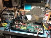
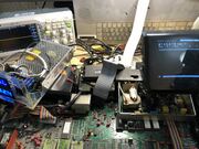
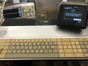
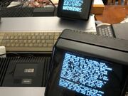
It's been a busy time for the Executels here over the last few weeks. I received a pair to look over before they got sent off to
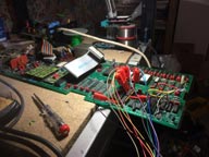
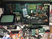
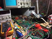
New Zealand, a 3910 main unit and 3911 Secretarial unit. Obviously the main unit didn't work so I dedicated several evenings and an entire week off work to fix it and to learn as much as I could about the startup sequence of these machines. I really need to document the repairs on my first machine as you can
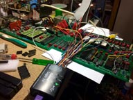
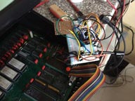
see in the earlier pictures, since I never got it to work and only had a 16 channel analyser at the time so digging deeper into things was difficult.
Anyway, on turning the 3910 on it made a folorn BEEEEEEEEEEEP which I've since learnt meant that it couldn't see the SAA5070 LUCY chip.
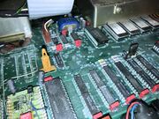
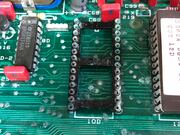
Fortunately I'd recently bought 5 of those so a quick swap showed a) the socket was badly damaged from the leaking battery as is the norm on these machines,
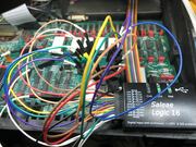
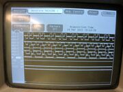
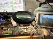
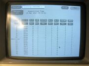
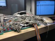
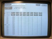
and b) there clearly was another fault since while the BEEEEEEEP stopped nothing else happened. These days I have a 136 channel HP1660A analyser so I quickly put
it to work dumping what the machine was doing at boot and I discovered it had lost the ability to read the ROM. The 8085a multiplexes the address and data
bus onto 8 pins, controlled by a signal on pin 30 called ALE which is high for data and low for addresses. These address reads weren't getting to the ROM
so I checked the 74LS373 which buffers the AD bus and found all the outputs were dead. Swapping that brought more activity to the bus but the CPU had lost
the ability to count. A replacement 8085 sorted that out but it was still looping in a RAM test. This was an ideal opportunity to bolster my 8085 coding so
I set about improving the RAM test routines I'd written for debugging my first machine. In troubleshooting those I discovered the top 1K of RAM
(0xFC00 - 0xFFFF) is mirrored with the screen RAM so any writes to it should be inhibited. That they weren't showed a possible problem which I traced to the
chip that controls this write disabling, a 74LS30 at location 8B. This is an 8-input NAND and it required all address lines for 0xFC00 to be high as well as
the SOD signal from the CPU. I wasn't providing the SOD signal in my code but I WAS trying to write to 0xFC00 and the test was failing because A11 and A12
were missing.
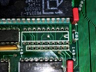
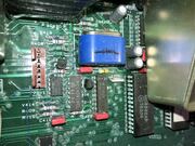
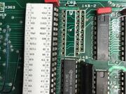
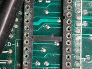
I'd had to replace the socket for the MC3242AP RAM multiplexer right next to the leaky battery, and in doing so had lifted a couple of
tracks. Turns out I'd missed re-adding those as patch wires so fitting them sorted THAT issue and the 74LS30 started working as expected.. Next was the
/MEMWR signal which is low to enable memory writes and in this machine it would never go low. Logic for this circuit is provided by a 74LS32 OR gate fed by /WR
from the CPU and a signal called /WREN which is the logical AND of /ALE with the output of the 74LS30 I'd just replaced (8B). It should go low as soon as /WR
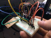
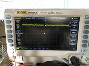
goes low at the CPU and it wasn't. Took me ages to find that though because the analyser would never show it. I swapped the chip and still had a
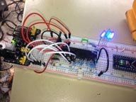
problem, 2nd replacement also had a problem. After breadboarding a test circuit to make sure both my replacements were good I put the scope on it and it DID
show a pulse, so RAM writes were happening.
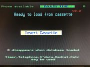
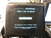
With a pulse at /WE on the RAM I could watch the code write 2 test patterns and read it back successfully, so I put the real ROM 1
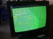
back in and booted... and it tried to access the tape! This is correct for booting so I quickly re-added the display only to discover a lack of SYNC on the TV
picture. A lot of troubleshooting and reading about the MR9735-02 viewdata chip showed it SHOULD be working but... wasn't. The chip can run in two modes
defined in the teletext world - On Hours and Off Hours. On Hours is used for TVs to determine if they're displaying a picture,
and the SYNC In pin (38) detects this picture. It is then put back out of SYNC OUT (37). In this instance SYNC IN is pulled high so the chip works in Off
Hours mode and generates its own sync based on the incoming system clock. This one didn't do that, so I swapped it with a known good one and got a display so
there's obviously a failure mode in these chips that means the external SYNC is lost even though the rest of the chip is working.
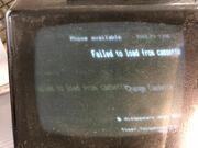
With all that in place I got booting attempts but it would fail to read the tape every time. A known good tape transport also had this
issue. It's not common for battery damage to reach the cassette microcontroller but in this case it had and the socket was encrusted with verdigris. No spares
at the time so I moved onto the OTHER 3910 I had on the bench. This one had worked initially but died while I was filming it. A quick run through with the
RAM test code showed it too wasn't getting a /WR signal at the RAM, again the output at 11B-6 was stuck high. A new 74LS32 for that and it was away, reading
tapes happily.
This only left the 3911 Secretarial unit. This is a simple machine in comparison to the 3910 and even takes its display via a direct
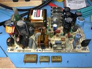
video feed. It has no actual processor and is run by yet another D8471, all keyboard entries are sent serially to the main unit. The PSU in this machine just
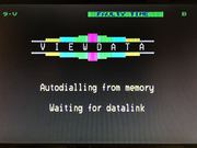
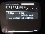
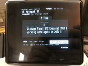
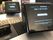
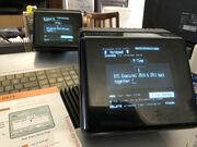
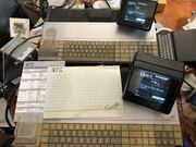
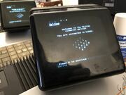
needed new smoothing capacitors and burst into life so all that remained was to hook up my SIP gateway and get them both onto the TELSTAR Viewdata highway!
 |  |  |  |
 |  |  |  |
 |  |  |  |
 |  |  |  |
 |  |  |  |
 |  |  |  |
Known Faults
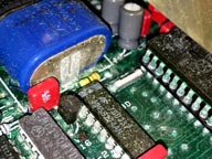
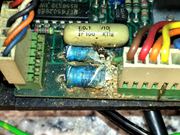
The biggest source of failure is components being eaten by the leaking MEMPAK (aka VARTA boardkiller). These backup batteries are
responsible for the deaths of countless machines from the 80s and early 90s and Executels in particular suffer badly from this, particularly the components
directly next to the battery like the MC3242AP RAM multiplexer, RTC, crystal and startup circuit. I haven't seen a single machine that's NOT suffered. First task
is nearly always to change the crusty sockets and clean affected chip legs. After that it's down to signal checking at various gate outputs and inputs.
The code itself has no error checking at all so if a component has gone bad or RAM isn't writeable the machine will get stuck in a very tight infinite loop.
Bear in mind for a successful power up you need a tape in the drive and the keyboard connected. With no keyboard the boot will fail.
Things to check
At boot the code does a delay loop counting from 0xFFFF down to 0x0000 to give the RAM and microcontrollers time to stabilise. Then it
zeroes all usable RAM from 0xC000 to 0xFBFF and finally writes 0x20 (space) to 0xFC00-0xFFBF. There is no error checking. Things to look for:
- Continuous sound from the keyboard speaker means LUCY is electrically dead. Check socket and fortunately spares are still available.
- 'click' at power up and nothing else. Long list here.
- 8085a
- /RESET (pin 36) should be over 3.6V. If it's not check the outputs of the 7611 op-amp (7D/1-6), 7D/2-3 and 6C-2.
- ALE (pin 30) should be pulsing. If it isn't then the address bus will also likely be dead meaning no ROMs have been found. Check sockets and ROMs.
- /WR (31) should be pulsing, as should S0 (29), S1 (33) and IO/M (34).
- 74LS373 (14B1, 14B2) all outputs should be pulsing. Check pins 2, 5, 6, 9, 12, 15, 16, 19. Check Clock (11) which is ALE from the CPU..
- /MEMWR (11B-6) should be pulsing. If It's stuck high check 10A-10 (/WREN), 6C-10, 8B-8 and 9A-3.
- 74LS30 (8B) controls access to the top 1K of RAM (0xFC00-0xFFFF) as it's mirrored with the screen RAM (2x 2114 at 15B,16B). For screen writing all inputs need to be high.
- RAS (16C-8), CAS0 (18C-3) and CAS1 (18C-8) should be pulsing.
- MC3242AP: COUNT (1), REF EN (2) and ROW EN (3) should be pulsing.
- If all those are present and it STILL won't boot you have a microcontroller issue, usually LUCY (6B) won't init and needs to be replaced. Spares can still be found on eBay.
- Garbage on screen with sync means the tape controller (4D/2) is missing.
- No sync on monitor means the MR9735-002 has failed and needs to be replaced. Spares of these are still available too.
Dismantling
Procedure for taking a 3910 to bits is here. CAUTION! Contains voltage warnings
as we're dealing with a high voltage CRT unit.
Memory Map
0xFFFF +------------------v-----------------------------------------------------v
0xFC00 |------------------^                                                     |
       |        Video RAM |                                                     |
       |                                                                        RAM
       |                                                                        |
       |                                                                        |
0x8000 +------------------+----------------------------------------------v------X
       |                  |  Bank 0        Bank 1        Bank 2          |      |
       |                  |  For 0x84000   For 0x94000   For 0xA4000     |      |
       |                  |  To  0x7FFFF   To  0x97FFF   To  0xA7FFF     |      |
       |                  |       Bank Switching in this area only       |      |
0x4000 +------------------+----------------------------------------------+------ROM
       |                  |                                              |      |
       |                  |                                            BASE     |
       |                  |                                              |      |
0x0000 +------------------+----------------------------------------------^------^
Microcontroller addresses
------------------------------
 Address bits    Active Chip
 A7 A6 A5 A4    Enable Signal
------------------------------
  1  1  0  0    /BANK SELECT
  1  1  0  1    /TAPE SELECT
  1  1  1  0    /LUCY SELECT (appears as 0xE3 in logic traces, code loops here if LUCY doesn't respond)
  0  0  1  1    Spare
  0  1  1  1    /KEYBOARD SELECT
  1  0  1  1    /CLOCK SELECT
  1  1  1  1    Nothing selected
Schematics
Executel schematics were originally (I'm guessing) on A0 sized sheets then reduced to A3 for the service manual. This means even after
high DPI scanning they can still be pretty unreadable so as I've gone on troubleshooting I've been redrawing them where necessary and also adding colour to
the sub-circuits, so the address bus, data bus, control signals etc are different colours to aid reading. Helps me anyway!
Timing and CPU
RAM and ROM
Tape microcontroller and RESET
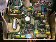
CRT board Schematic
CRT board Layout
Service Guide Chapter 9, Video
Full set (up to now, LUCY is missing) in an 18mb ZIP.
Timing and CPU
RAM and ROM
Tape microcontroller and RESET
CRT board Schematic
CRT board Layout
Service Guide Chapter 9, Video
Full set (up to now, LUCY is missing) in an 18mb ZIP.